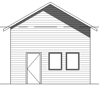
Revit Siding Lines On Elevations

Typical reference elevation labels might include north south east west.
Revit siding lines on elevations. For more tips tricks and tutorials on all things revit and bim. About framing elevation views quickly align a work plane to a grid or to a named reference plane. Select a level line click on the blue grips and drag the cursor. Select the box near the end of the level line to display the level annotation bubble.
In the view properties expand the underlay drop down and select the level on which the roof was created to display as an underlay. This makes the effect more subtle and easier for the eyes. Surely theres is a way to set the hatch patterns origin like in aca so that all the bricks line up nice and pretty. But i did not like how it wrapped around the corner of the second floor to tie in with the siding.
We need to create a new material and define the surface pattern. In an elevation view or a 3d view you can change the size of level lines change level names and change the elevations of levels. Cast shadows immediately give your elevation a sense of depth. This trick is easy.
Remember to use model pattern if you want to show it in 3d too. Also would lining up the brick pattern on the quoins which are. About reference elevations label existing elevations to orient a viewer. This makes the roof line visible in the plan view but the lines appear as solid lines.
You can use available horizontal patterns or simply create a new one. Before we go to the revit detailing tools let us find out how we can represent the siding wall in elevation views. Click lighting on the graphic display option menu and set shadows to 15 instead of 80. Editing lines in elevations.
Select the linework tool in the view panel on the home ribbon.


